Gradient Infill for 3D Prints
Infill structure is the lattice material that is placed inside of your 3D prints so that you don’t have to print them 100% dense and therefore using a lot of material and time, where it’s often not needed. Infill comes in lots different varieties and I’ve tested many of them in the past already. There hasn’t been a lot of things going on over the recent years besides the current hype of gyroid infill which is a good choice for some applications but also not always.
If you’ve ever had a course in mechanics or just use a bit of common sense you know, that most mechanical parts are loaded the highest on their outside and way less in the middle. Look at a simple beam under bending. You have tensile stresses on one side of the part and compressive stresses on the other. In-between there is a gradient with even one location where the stresses are zero. If we 3D print our part it will usually have a closed outer shell and then a sparse infill structure in the middle. For our bending beam this means, that the infill is not loaded equally. The parts closer to the shell are more loaded than the center. Ideally, we’d need more material around the perimeter than in the center but conventional infill doesn’t give us this possibility. This is a simple example but besides some very specific cases like pure tension, pure compression or herzian pressure it’s almost always the case that the core of parts is less loaded than the outside.
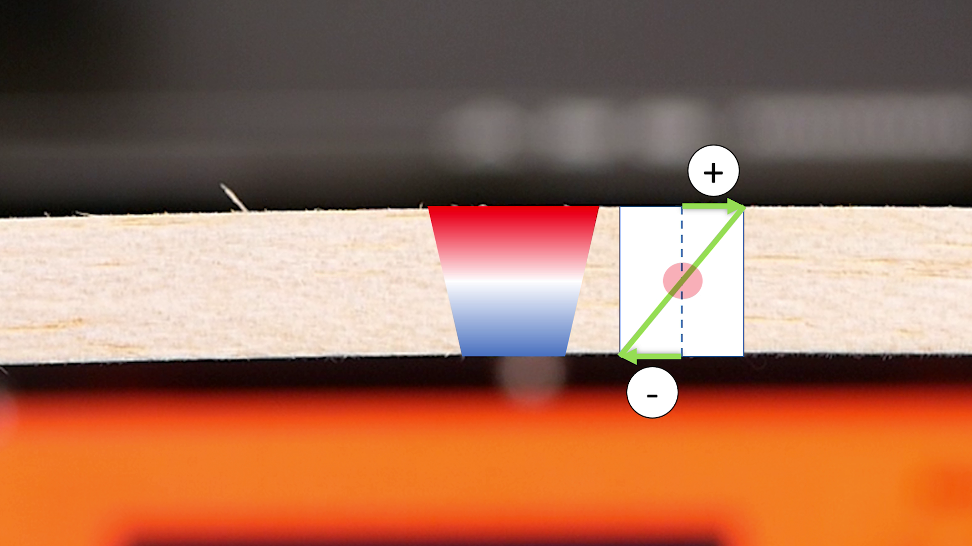
Beam under bending
In the past I’ve already tried to tackle this problem by my Smart Infill method where I simulated a part using finite elements and applied mesh modifiers to increase infill at the location where it’s needed the most. This method works, but is kind of complex and not implemented yet in any slicer. Wouldn’t it be great to have an infill that gradually gets more sparse the further into the part it gets. CURA has its gradual infill but that’s more for getting better top layers with less infill in general. Kisslicer now has dynamic infill, that allows you to change the infill ratio using a greyscale image. Pretty cool, but not 100% what I had in mind and unfortunately only available in the currently $82 premium version. I’ve been doing a couple of videos about extrusion width in the recent past which basically is the parameter of how wide the line of extruded material is, after it leaves the nozzle. During these investigations I noticed that it’s possible to extrude lines of material way wider than the diameter of the orifice. Values of 300% and more are quite doable and even values below the nozzle size are possible.
Now, the idea that I had was, if it’s possible to use the variability in extrusion width to dynamically modify the amount of material that is coming out of the nozzle while printing the infill. This way I could put more plastic next to the walls and reduce flow in the center with existing patterns and only minor flow modifications. In order to implement that I didn’t write or modify any slicer but since CURA for example puts comments in the GCODE where infill, perimeters and similar start I thought it might be possible to just write a simple parser and post-process existing code. Therefore, I coded a small script in Python. The idea was to first read out the perimeter lines in a layer and then calculate the distance of each infill segment to the closest perimeter. I first started with the gyroid infill because this type of structure consists of many individual line segments. Each line segment is represented very simply in GCODE. G1 means linear move from the current position, X and Y define the next position and E tells the printer how much filament will be fed during that move. So each line segment is built up from the previous and next position. For each I calculate the center and then search for the closest distance to the outline. I defined a maximum and minimum extrusion multiplier as well as a gradient thickness. If the distance is within the gradient thickness, I just interpolate between the min and max value, if it’s bigger, I use the minimum value. In my tests I mostly used a range from 300 to 50 or even 0% and a gradient thickness of 3 to 10mm. With this method I basically ended up with the same GCODE file in the end, only the extrusion amounts are slightly adjusted for the infill.

Dynamic extrusion width for graded infill
Unfortunately, most other infill types like rectilinear or triangle are not composed of these small line segments so the algorithm doesn’t properly work because I can’t resolve a gradient with just one point. For this reason, I implemented a second variant, that chops the line infills in around 1mm segments and calculates distance and extrusion amount for these individual ones. For those infills the gcode files become bigger but I didn’t notice any performance differences due to the small segments. And damn, the results do look really nice, just as I intended.
Before I started with the material tests I played a lot around with individual settings and printed samples on my Original Prusa i3. The adjustments of flow during printing require quite a fast-reacting extrusion system where a direct extruder is definitely an advantage. And for this one it works really well. You sometimes notice slight slipping of the filament but that can be tacked by slightly higher temperatures or slowing the prints down a little. Even though it might be hard to imagine, but I currently don’t have a single Bowden extruder printer at home so I couldn’t test if it also works for those. I’ve put a couple of sample files in the description so it would be great if you give one a try and let me know how the results turn out.
For testing if this gradient infill is really more efficient, I printed two different sample types: my usual test hook and also a simple bending bar with which I’ll perform a 3-point bending test to analyze the stiffness. I varied settings a bit so that we can later compare how the results are at similar printing time and at similar weight of the parts, because for thin structures, gradient infill usually results in heavier samples.

3-Point-Bending Test Samples
For the bending bar I started with a part that had 30% rectilinear infill and post-processed it with a flow range of 25-300% and 4mm gradient thickness. I also tested 45° and 90° infill orientation. The parts nicely show that the infill is denser on the outside and sparser on the inside. The gradient infill parts weight 30% more in the end. I also printed out a 30% infill part without post-processing and a 46% part that had the same weight as the gradient infill parts. For the 3 point bending test I loaded them successively in the middle with, uhh, “calibrated” soda cans and marked the displacement so that I can calculate the bending stiffness in the end. The results are really nice and show that stiffness at the same weight is almost 30% higher with the gradient infill. For this I compared the beams that had the same weight. If we take a look at the stiffness that we can achieve during the same amount of printing time, we are almost 60% stiffer! Here I compared the 30% normal infill beam to the gradient infill parts, because with this method we don’t add any additional printing time. Take this with a grain of salt because depending on the shape of your part and the settings, your results may vary!


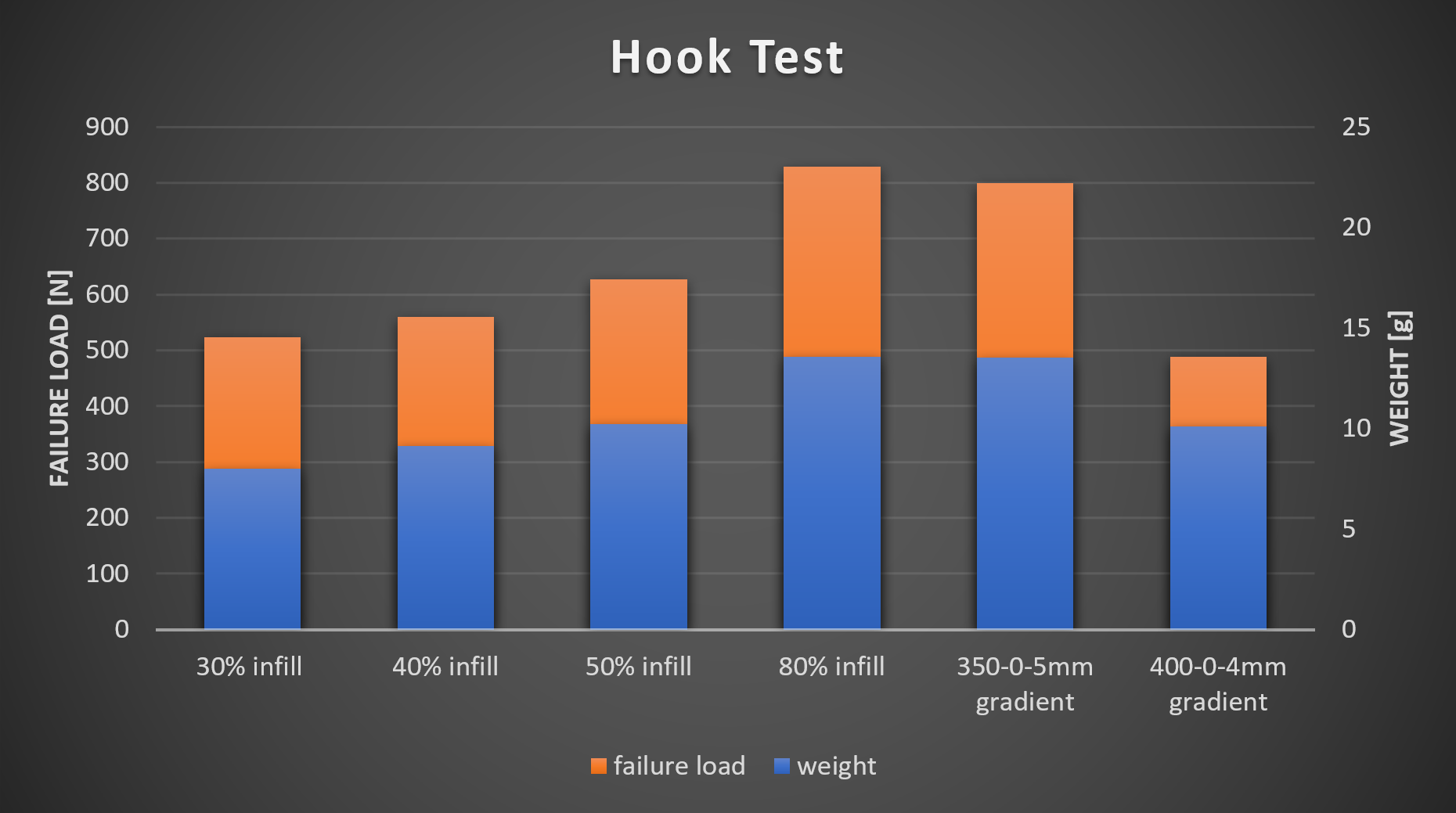
For the hook I also printed a couple with different infill ratios and then applied gradient infill to the one with 25% infill. I then tested all of them on my DIY universal test machine where unfortunately I didn’t find a significant improvement over just increasing infill ratios. The reason here is that I add lots of material in areas where I wouldn’t actually need it. I will play around a little more with settings and see if I can improve something, but for such small parts it might not be a great benefit, at least in the current form. What I want to implement though is something similar as with my smart infill. I want to take the results of a Finite Element Analysis, be it Stress or Topology and map those results on the infill density by adjusting flow and not using modifier meshes, and this, in all 3 coordinate directions. I’m quite interested how that will perform!
I think these results show that this gradient infill method might not be the new perfect infill method but it would definitely be beneficial for a lot of our parts to improve the material use, strength and stiffness. Just a step forward in the right direction and maybe someone of you has an even better idea how to use or improve it! I’m just the guy that spreads ideas. You’re the ones that can be inspired by those ideas and take them to the next level.

In-efficiency of Gradient Infill if the load case is unknown (right: 3D print, left: von Mises stresses)
If you also want to try out on your own than you can find the Python script fully Open Source on my GitHub. I invite anyone to contribute and improve on it because I’m a mechanical engineer and not programmer. Oh, and did I tell you that I also lack the time to focus strictly on one project? If you’re new to Python, you could start learning this programing language using this videos sponsor Skillshare or just download and install Anaconda, copy the script file and your Gcode in the same folder, open the script using Spyder IDE, adjust the settings and hit run. This shouldn’t require anything else. A more detailed description is also available on my website. Currently the script only works with CURA due to the section comments it puts into the gcode and also make sure that you print the perimeters before the infill and activate relative extrusions, otherwise you might run into problems. Let me know what you think of this new infill type down in the comments and make sure to contribute on the Github if you can improve my work! What I’d really like to see, is this being implemented in a real Slicers because then it would be as easy to use for everyone as any other infill and since the slicer itself has more information about the model being processed you could also add a gradient in z-direction and not only in the XY-plane as I’m currently doing it.
Source Code: https://github.com/CNCKitchen/GradientInfill
CURA gradual infill: https://ultimaker.com/en/resources/52670-infill
Kisslicer dynamic infill: https://www.sublimelayers.com/2019/05/dynamic-infill-density-in-new-kisslicer.html
How-to use Guide
If you’ve never been programming in Python before, here’s a short guide on how get you up and running so that you can post-process your own G-Code files.
There are many ways how to get Python running on your system. One very easy solution is Anaconda that provides you a whole development suite to code and run Python. Download it from their website and install it:
https://www.anaconda.com/distribution/
The GCode files from CURA are the only ones that can currently be processed. I sliced my parts all with CURA 4.4 but other versions should work as well. You can use your normal profile, only make sure that:
“Infill Before Walls” is NOT activated!
“Relative Extrusion” IS activated!

Infill Before Walls

Relative Extrusions
Copy the Python script AND your G-Code file into the same folder:

Now open the Spyder IDE (which was installed with Anaconda) and open the addGradientInfill.py script.
Make sure the variable gcodeFile contains the name of your unmodified G-Code file from CURA.
Define outputFile and assign a different name is the input file. This will be the name of the G-Code file after Gradient Infill has been added.
Set the parameters to your desire and according to the comments in the script.

Select the green play button to run the script and after a couple of seconds (to minutes, depending on the file size) you should have a processed G-Code file with gradient infill.
