The effect of Extrusion Width on Strength and Quality of 3D prints
Most of us probably change the layer height we print with quite a bit and adjust it depending on if we want something fast or nice. A parameter that I don’t see many adjust is the extrusion width the slicer uses. And at this point I’d be really interested if you ever touched it and why. Let me know in the comments! The extrusion width is how wide the line of material that is printed is. Please don’t mix that up with the extrusion multiplier! The extrusion multiplier only adjusts the flow of material but keeps the distance between tracks the same, extrusion width sets the distance between extruded lines and adjusts material flow accordingly. Most of us probably use a 0.4mm nozzle on our machines and the width of the filament line doesn’t necessarily need to be exactly that value. Going smaller might seem a bit counterintuitive but is actually possible and can even be beneficial for quality. Most slicers use a standard value of 100 to 120% of the nozzle diameter. This means the material extrusion is as wide as nozzle orifice or just a bit wider. Since the nozzle tips have a bit of flat area around the hole the layer height will be kept and the material will not be squeezed upwards. Also, if I later talk about extrusion width, I will usually use the percent value which means what percentage of my 0.4mm nozzle diameter. Some slicers like Cura hide extrusion width by default and let you define the wall thickness which doesn’t necessarily need to be a multiple of the extrusion width. For full control over that value I used PrusaSlicer 2.1 for all prints.
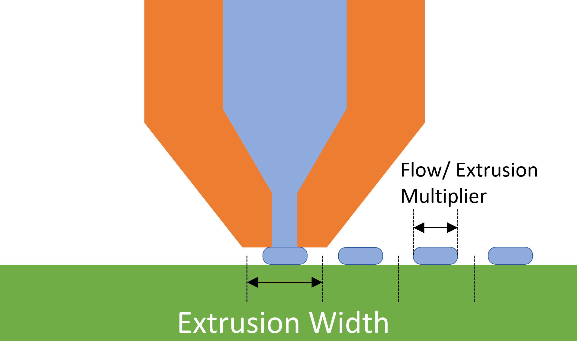
Extrusion Width VS Extrusion Multiplier / Flow
With higher extrusion widths the pressure inside of the nozzle needs to be higher as well to squeeze the material to the sides after it leaves the nozzle. This additional pressure does not only squeeze the material to the side, it will also press the individual layers together more which poses the question if that also helps with the layers bond together better?
This is exactly the task of todays video. In order to investigate that question I printed 3DBenchys for quality assessment and layer adhesion samples as well as my test hooks for strength testing. I thought it would be interesting to even start from extrusion widths smaller than the nozzle bore up to really high values. I printed all parts with a 0.4mm nozzle and started at 90% extrusion width and went all the way up to 250%. That’s 0.36mm to 1mm and the latter is the diameter of the nozzle tip of a standard E3D nozzle. Pay attention if you use different nozzles for example the MK8s of the CR-10 and all its variants and clones because their nozzle tip looks different which has advantages and disadvantages. The parts were printed on my Original Prusa i3 MK2S in SpoolWorks PLA at a nozzle temperature of 210°C, 50% fan and 0.16mm thick layers. In order to have ambient temperatures as constant as possible I had the printer in my basement where I have a quite consistent temperature of 20°C. Each printjob for one extrusion width consisted of one 3DBenchy and a pair of 3 layer adhesion specimens. The 3DBenchy and the test samples were printed sequentially so that the layer times were consistent and didn’t jump.
At first, let’s take a look at the print quality. It was very interesting to see how all 3DBenchys looked basically the same up to 140% extrusion width. Even the model with 90% width didn’t look differently. At 160% I was slowly able to spot artefacts in the overhanging regions probably because the material is squeezed out that much. At 250% the whole surface was even strangely textured. At 200% and higher the flag pole base just vanished not because of printing problems but because the part just had too thin walls to be printed with a 0.8mm extruded line. At higher extrusion widths some areas looked as if they were a bit underextruded though I think was only the overlapping areas with the perimeter that needed tuning. All in all, the printable range is way bigger than I initially thought and 150% width still seems reasonable. You have to keep in mind that especially thin areas might suffer faster in quality, because the additional extrusion pressure will create a downward-force on the part, squishing it together. Also, the additional material will add drag between the nozzle and the part and therefore might deform it due to the shear forces or cause other issues. Another thing that you have to keep in mind is that with thicker extrusions you also pump out more material in the same amount of time that needs sufficient cooling. In the worst case you might even get to the limit of your hotend where it’s not able anymore to melt the material properly causing even more issues. In such a case it might be a good idea to take a look at hotends like E3Ds Volcano or just bump the temperature up a little.
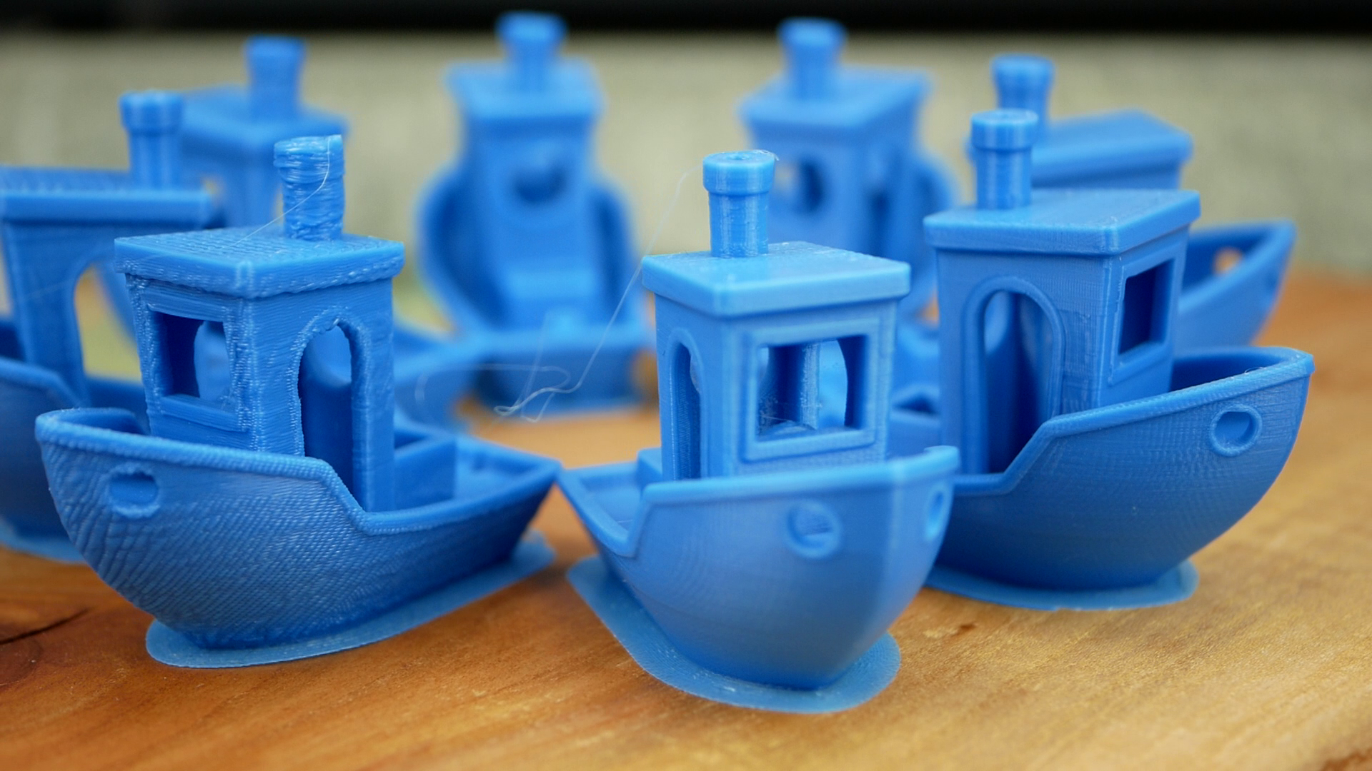
3D Benchies printed at different extrusion widths
Let’s now continue with the layer adhesion tests. The samples that I printed were measured and then mounted in my DIY universal test machine where they were are all loaded at a constant speed until failure. This should give us very comparable values because it removes the human factor. Here again, the samples up to 140% extrusion width looked very similar and only at wider extrusions some problems seem to occur. For statistics I tested 3 samples for each setting and I didn’t test them in order to avoid any systematic error. The results are very interesting because we can clearly see that the layer adhesion slowly rises from 90% to the maximum probably at 150%. After that it falls again but the reason for this behavior might also just be that the samples got really rough and the stress risers on the surface caused premature failure. Just for a reference, the pure material strength is at around 60MPa so even though the layers seem to adhere better we are still a bit away from perfect fusing of the layers but again, a bit closer. As I already mentioned in the last video this is actually a video series where I analyze the influence on strength of different printing parameters and then ultimately want to combine them to get the maximum strength out of our 3D printed parts. Design of Experiements if you know what I mean. If you don’t want to miss that, make sure that you’re subscribed and have also selected the notification bell!

Strength of layer adhesion samples printed with different extrusion widths
At the lower extrusion widths, the crack planes are only over one or two layers and they become more un-uniformly the more material is squished out. Another indication that we’re on the right track.

Cracked sample printed with 100% extrusion width
Next, in order to apply that to a real problem I also printed a couple of my test hooks to see if our findings on the simple layer adhesion samples also hold true here. All in all I printed 12 parts, all standing. 3 had 2 perimeters and 100% extrusion width. 3 had the same number of perimeters but at 200% width, doubling the wall thickness. 3 were printed with 4 perimeters and 100% width resulting in the same wall thickness. 3 were right in-between with 3 perimeters and 133% extrusion width. Of course, the parts with thicker walls will be stronger, but is it better to use more perimeters or thicker extrusions. By the way, I did a whole video on why you should make your parts stronger by adjusting perimeters instead of infill ratio. Card up here! Besides strength I also noted down printing time and weight. I, for my part work in aerospace and am impatient. That means that for once, I want the most strength per weight and the strongest print in the shortest amount of time. Some might argue that print time doesn’t play a role for them so by just using more perimeters and infill they make their parts stronger. But still if you’re someone like this then having even stronger parts with wider extrusions might be a bonus on top.
The quality of the hooks wasn’t as different as with the 3DBenchies and the layer adhesion coupons. Even the 200% sample still looked okay. Since I only used 20% infill there always was a bit of space left the push the surplus of material. So as suspected, the hooks with only two perimeters failed at first at around 20kg of load. Next were the hooks with 4 perimeters and 100% extrusion width at 33kg but with quite some scatter. Second came the parts with 3 perimeters and 133% extrusion width at 37kg of failure load and the strongest ones were actually the ones with only 2 perimeters and double the normal extrusion width at 39kg on average. This is almost double the strength with the same printing time when we compare it to the first sample. The printing time was even lower because the infill is thicker so less lines need to be extruded. So, if you are as impatient as I am, then thicker extrusions will give you stronger parts in the same amount of time. If you are looking for parts that use the given material as efficiently as possible, thicker extrusions will help you in this regard as well because layer bonding will be better. Pretty cool, huh!

Strength of the test hooks printed at different extrusion widths
So, what’s the verdict? We have once again learnt that the strength of our 3D prints is not only a result of the materials we use but also the settings. Using wider extrusion seems to help layer adhesion because the material is squished more into the previous layer. At some point you run into quality problems but to be honest, that’s usually not the biggest concern with mechanical parts. If you need a strong part quickly then upping the extrusion width is almost directly proportional to the gain in strength, which is really cool! You might have the same advantage with a bigger nozzle, but this method saves you the hassle to switch all of the time. Just keep in mind that you will extrude more amount of material in the same timeframe so make sure your hotend and cooling setup is able to handle that.